


From Simple Measurements to Smart Spatial Solutions: Discover How the Makagic L7 Transforms Your Workflow

- High Accuracy – usually within ±1–2 mm
- Fast Results – less than a second to measure
- Portable Design – small enough for one person to use
-
Multiple Functions – calculates distance, area, volume, and more
How Does a Handheld Laser Measurer Work?

Distance = (Speed of Light × Time) / 2
D = (c × Δφ) / (4πf)

Where:
- Δφ is the phase shift between transmitted and received signals
- f is the modulation frequency
- c is the speed of light
System Architecture:
- Laser Emitter + Modulator (DDS)
- Receiver (APD – Avalanche Photodiode)
- Signal Processor (MCU + ADC)
- Display and Communication Module
Technical Challenges and Solutions:
- Phase Ambiguity: Solved using multi-frequency modulation
- Temperature Drift: Mitigated with compensation circuits and precision op-amps
- Sampling Accuracy: Enhanced with high-resolution ADCs and optimized algorithms
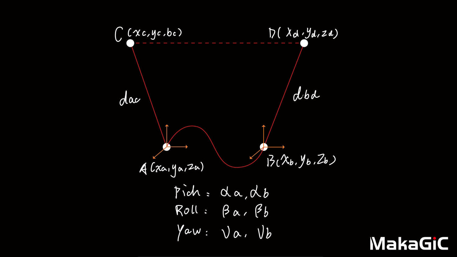
3. Triangulation
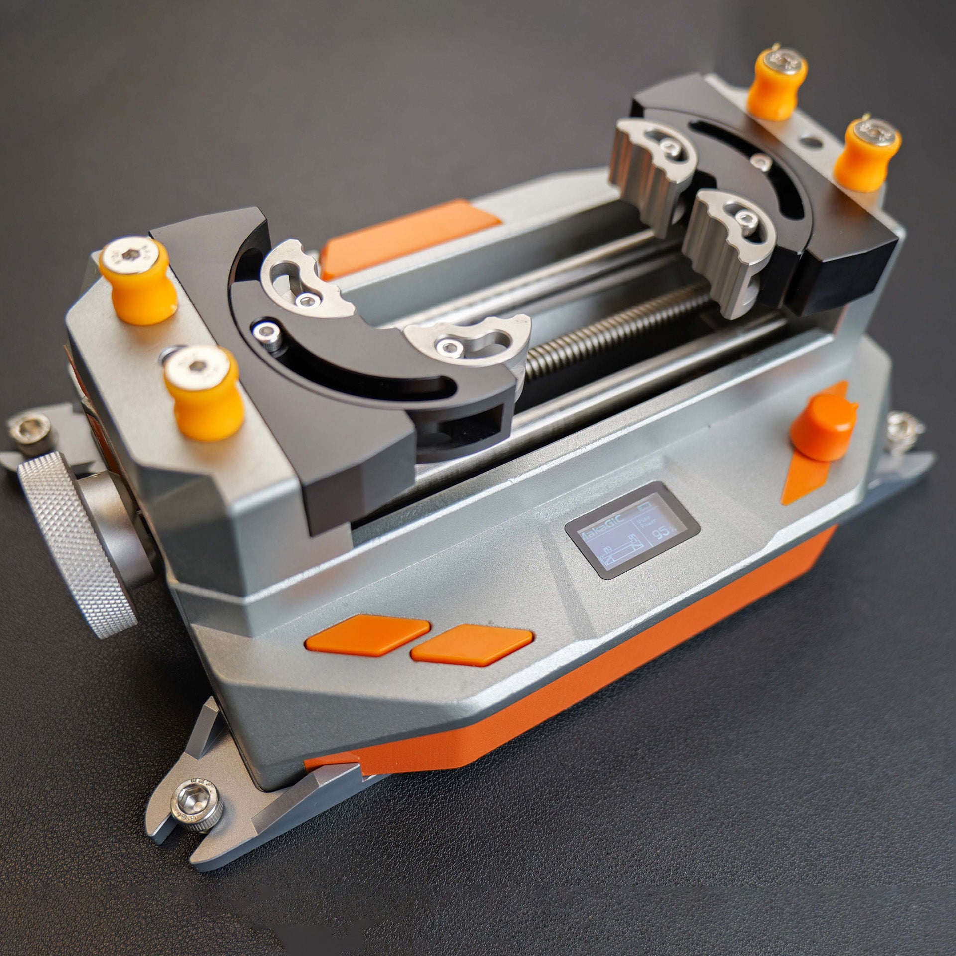
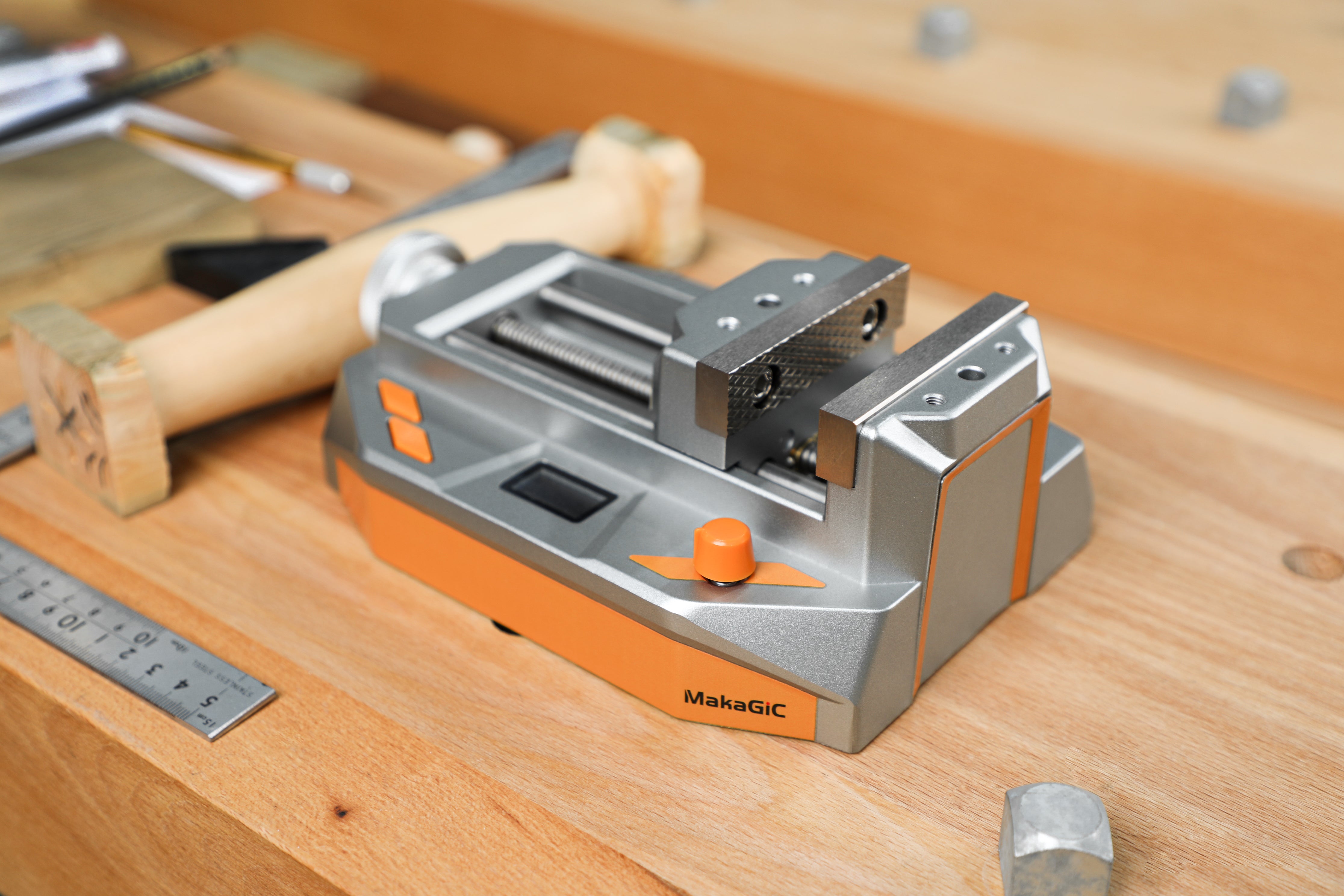
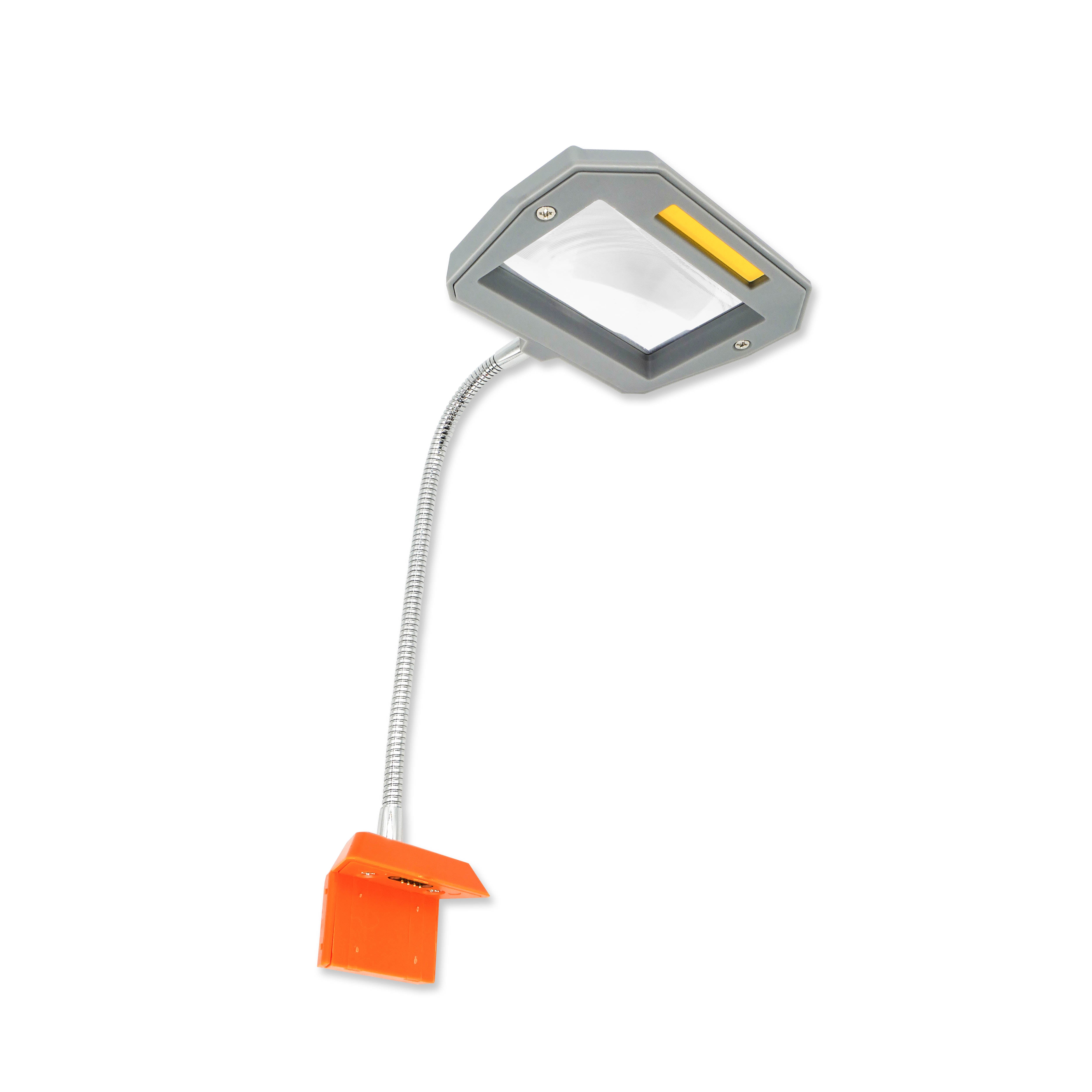
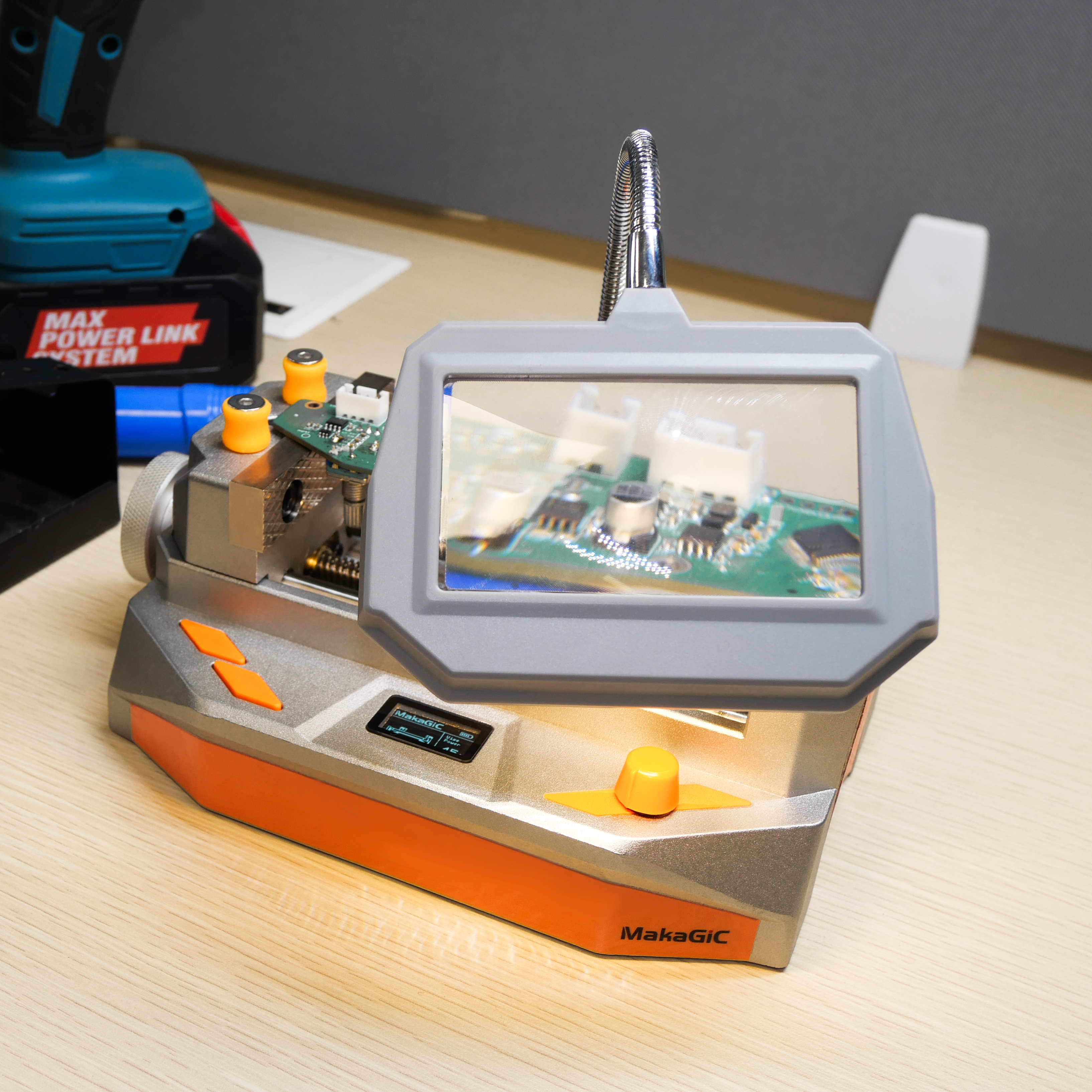
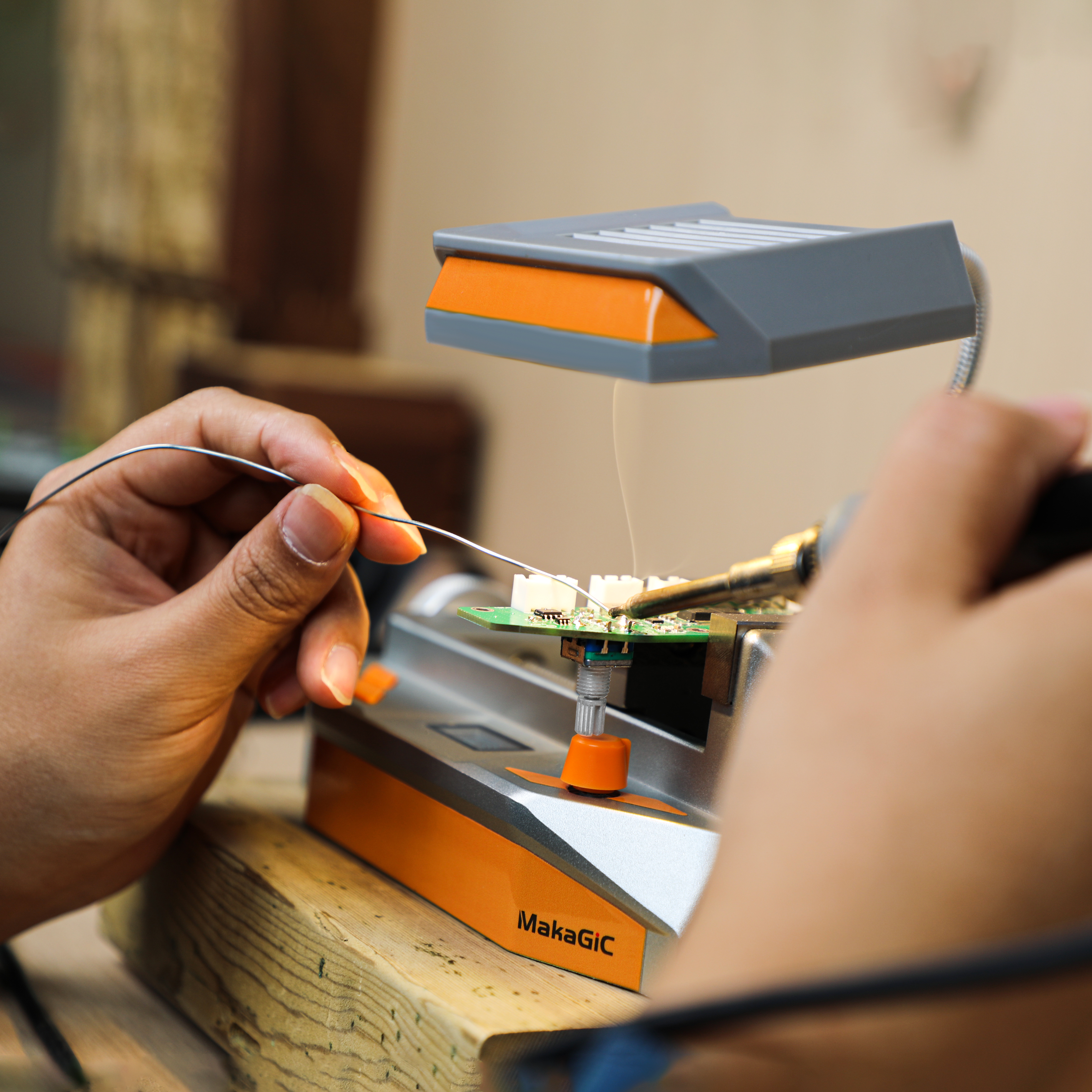
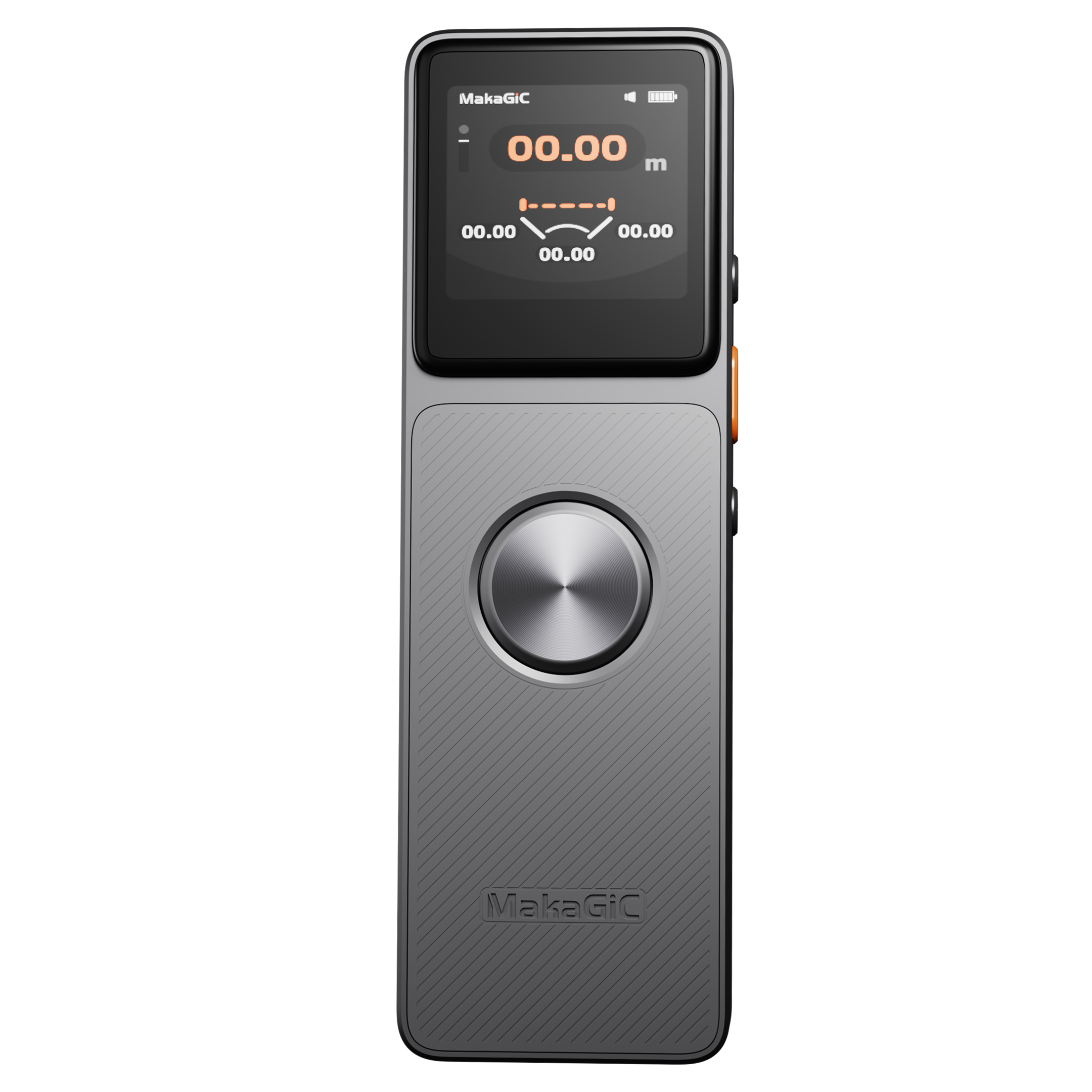
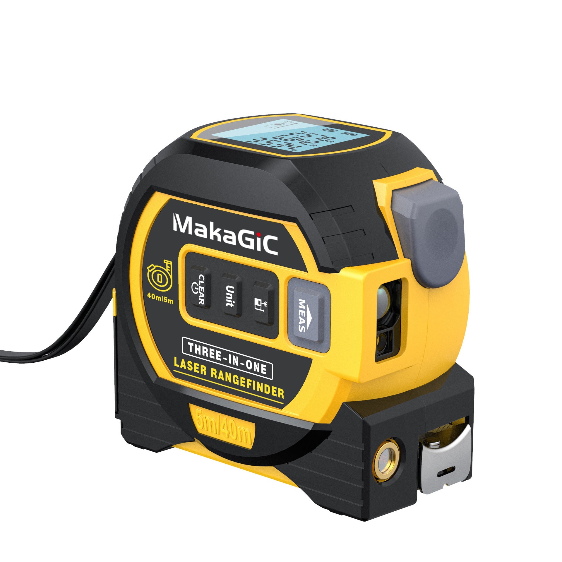
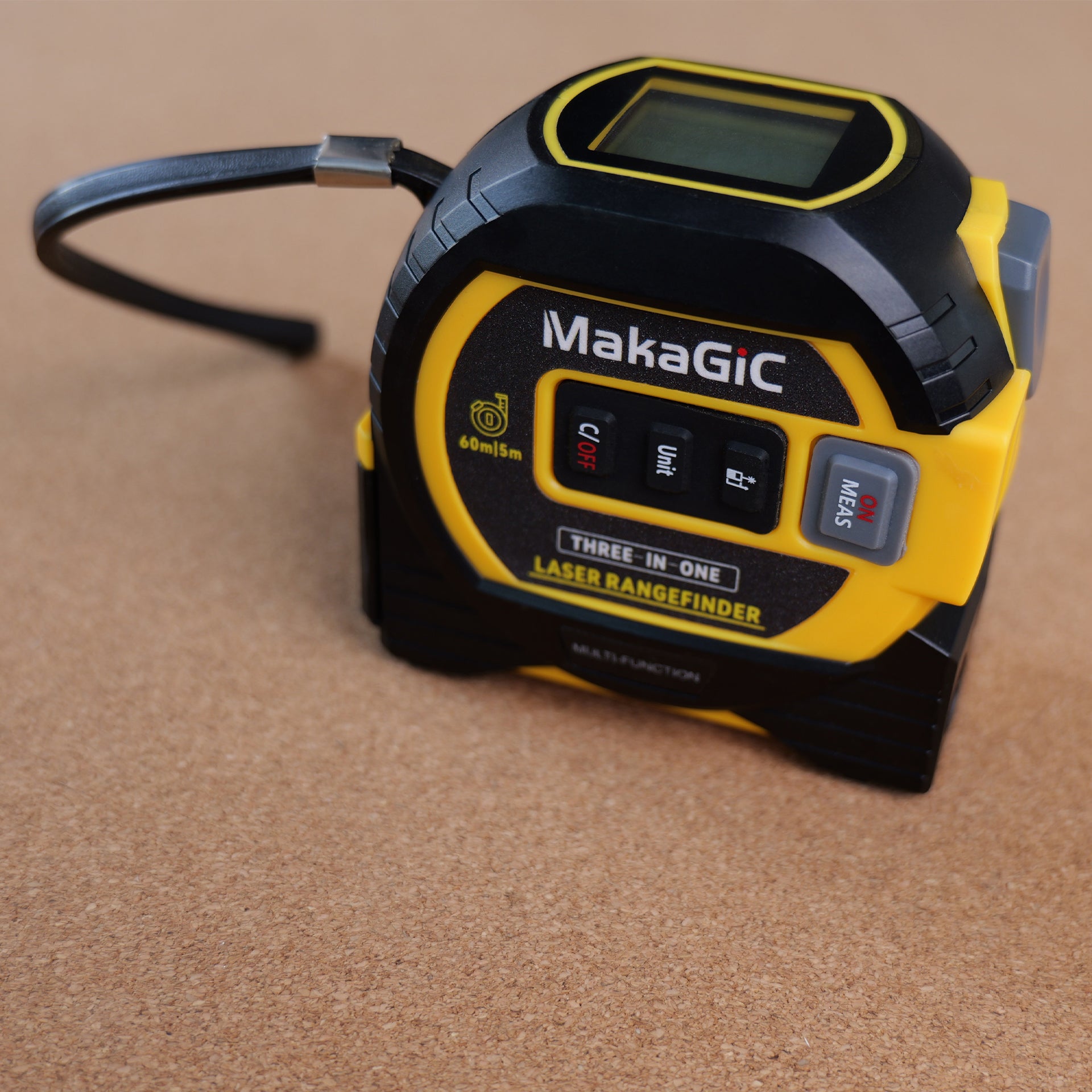
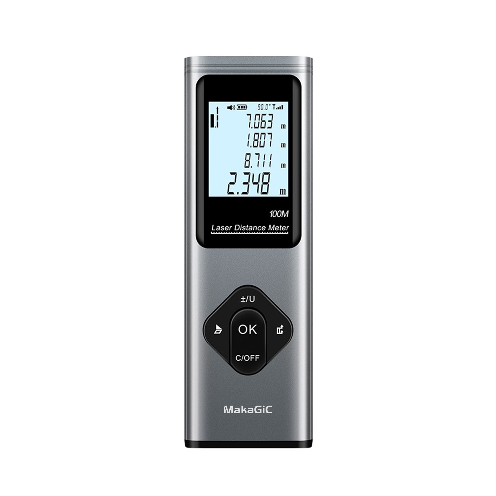
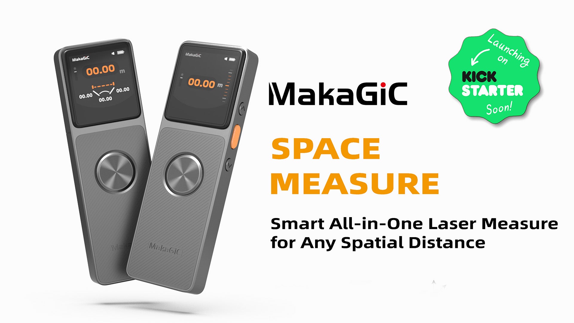
Introducing the Makagic L7

-
📏 Rangefinder – Measures distances quickly and precisely, whether it’s a small room or a long outdoor span.
-
📐 Inclinometer – Checks angles and slopes, perfect for construction layouts or furniture placement.
-
🧭 Level – Ensures surfaces, shelves, or frames are perfectly horizontal or vertical.
-
⚙️ Tachymeter – Helps with advanced spatial measurements, especially in industrial or professional engineering projects.
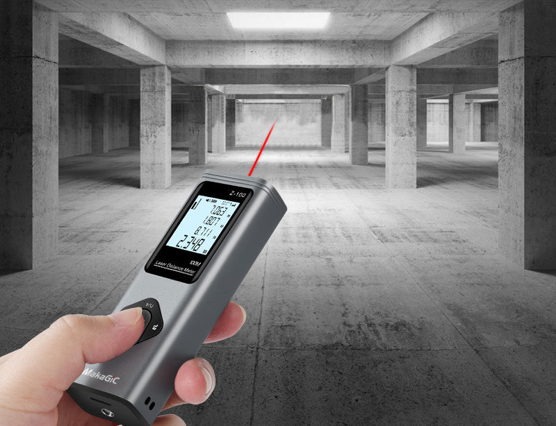
Advanced Technology: Omni Dimension 1.0

-
Measure with hand gestures without touching buttons
-
Get faster readings for large areas or complex structures
-
Maintain high accuracy, even in challenging environments
-
🏠 Home Renovation: Quickly measure walls, doors, or windows for furniture or cabinets.
-
🏗️ Construction Sites: Accurately lay out building foundations or check angles on beams.
-
🖼️ Interior Design: Ensure pictures, shelves, and décor are level and perfectly spaced.
-
🏭 Industrial Applications: Map large machines or factory layouts with precise spatial data.


A gyroscope itself cannot directly measure azimuth. In essence, a gyroscope is a “relative measurement device” that only outputs angular velocity (unit: °/s), i.e., “the rate at which an object rotates about a given axis”. Azimuth, however, is an “absolute angle” (relative to a fixed direction of true north), determined by combining an initial heading reference and integration calculations.

1.Definition of Angular Momentum
Angular momentum (symbol L) is a physical quantity describing an object's ‘inertia of rotation’, analogous to ‘momentum (mv)’ in linear motion. For a rigid body rotating about a fixed axis (such as a gyroscope's rotor), the angular momentum formula is:
L = I × ω
I: The moment of inertia of the rigid body (related to the mass distribution and shape of the rotor; the greater the mass concentration towards the periphery, the larger I);
ω (Omega): The angular velocity of the rotor (the faster the rotational speed, the greater ω).
Angular momentum is a vector quantity whose direction follows the right-hand spiral rule: grasp the rotation axis with your right hand, point your fingers in the direction of rotation, and the thumb indicates the angular momentum direction (e.g., for a clockwise gyroscope, angular momentum points downwards perpendicular to the plane of rotation).
2. Law of Conservation of Angular Momentum
In an ideal scenario without external torque, an object's angular momentum remains constant in both magnitude and direction—this is the Law of Conservation of Angular Momentum. Gyroscopes exploit precisely this property: by causing the core component (rotor/oscillating mass) to spin rapidly or vibrate continuously, a stable angular momentum is established. When an external object (such as a carrier) rotates, the angular momentum ‘resists’ changes in direction. By detecting this ‘resistance effect’, the rotational state of the carrier can be inferred.
3. Key Effect: Precession
When subjected to external torques (such as gravity or torques generated by the carrier's rotation), the angular momentum does not rotate directly along the torque direction. Instead, it undergoes a ‘slow rotation’ around a direction perpendicular to the torque. This phenomenon, termed precession, constitutes the core effect enabling gyroscopes to detect rotation.
Signal Processing and Applications: From Physical Quantities to Usable Data The raw signals output by a gyroscope (such as capacitance changes, optical path differences, or frequency differences) cannot be utilised directly. They must be converted into standard digital signals (such as angular velocity or angle) via ‘signal processing circuits’ and ‘algorithms’, then integrated with specific application scenarios to achieve functionality.

Signal excitation: Driving the mass block/laser of the solid-state gyroscope;
2. Signal detection: Capturing minute variations (displacement, temperature, frequency) generated by the Coriolis force via sensors;
3. Signal amplification and filtering: The raw signal is weak and noisy, requiring amplification through an amplifier and removal of environmental interference (e.g., temperature drift, vibration noise) via a filter circuit;
4. Analogue-to-digital conversion (ADC): Transforms analogue signals into digital form for transmission to the microcontroller unit (MCU);
5. Algorithmic correction: Applies ‘zero offset compensation’, ‘temperature compensation’, and ‘linearisation correction’ algorithms to eliminate systematic errors, outputting high-precision angular velocity/angle data (typically in °/s or °).
Azimuth technology finds extensive application in the L7's level and inclinometer functions. It translates the principle of water displacement in traditional spirit levels—where a water bubble shifts under Earth's gravity—into electrical signals. Defining levelness through data offers greater precision and clarity than physical methods.
Furthermore, signal processing ensures calculated data remains precise and stable, enabling rapid response. When the hand moves to a stationary position during distance measurement, the sensor immediately captures accurate data for computation. This eliminates the need for repeated presses of the measurement button to obtain precise readings, with negligible error.
High precision remains the core characteristic throughout. This is achieved not only through the digital reconstruction of traditional measurement principles but also relies on comprehensive optimisation across the entire chain—from signal excitation to algorithmic correction. This culminates in an experience where ‘measurements are precise and controllable in any scenario and across any dimension,’ completely overcoming the limitations of traditional tools, which are often accurate in specific scenarios but prone to deviation across multiple scenarios.
 To comprehensively and accurately validate product performance, we meticulously selected three representative prototypes and subjected them to systematic and detailed testing.

During testing, we rigorously controlled variables to obtain data from 20 distinct operating conditions, meticulously documenting each dataset with precision. The corresponding results are clearly presented in the charts. To illustrate product performance more intuitively, we have plotted a line graph. The graph clearly demonstrates that across all 20 test sets, the measured values from the three prototypes deviated minimally from the actual value (2.74m), with the error range strictly confined within 0.05m. This underscores the exceptionally high precision of the testing, ensuring each data set accurately reflects the product's true performance characteristics. This provides precise and reliable foundations for subsequent analysis and optimisation of the product's capabilities.

More crucially, L7 employs end-to-end signal processing to transform ‘high-precision sensing’ into ‘high-precision data output’, ensuring negligible error in any measurement scenario. for high-frequency vibration noise (e.g., hand tremors), it activates the high-frequency filtering module; whereas for temperature drift interference (such as moving from a cold exterior to a warm interior), it triggers thermal drift suppression logic. This ensures amplified signals retain only valid information related to angle and distance, controlling environmental interference errors to within 0.0005°.
The L7 employs a 24-bit high-precision ADC chip, offering 256 times greater sampling accuracy than the 16-bit ADCs found in conventional measurement tools. Even angular variations as minute as 0.001° within the signal are precisely converted into digital data, preventing ‘data distortion’ caused by insufficient conversion precision. The final algorithmic calibration stage constitutes the core safeguard enabling the L7's ‘all-scenario high precision’.
For different measurement dimensions, the L7 employs customised calibration models: during angular measurement, ‘multi-temperature zone dynamic zero drift compensation’ continuously corrects the sensor's inherent zero drift error in real time. Even during prolonged operation, zero drift is maintained within 0.0005°/h, ensuring consistent precision from power-on to power-off for every angle measurement.
This end-to-end precision control ultimately translates into a user experience where ‘no cumbersome operations are required, and every measurement is accurate.’ L7 demonstrates through technology that high precision should not be a ‘privilege reserved for specific scenarios,’ but rather the ‘standard for every measurement.’
It empowers users to effortlessly obtain reliable data in any environment without worrying about errors, which lies at the heart of its redefining the value of measurement tools.

It is precisely through the L7's deep integration of multiple core technologies that it breaks free from the limitations of traditional measurement tools – their single-functionality and compartmentalised scenarios. It achieves unified precision measurement across five key dimensions: distance, area, volume, angle, and rotational speed.
This elevates the measurement experience from ‘cumbersome adaptation’ to ‘one-stop precision and efficiency’. This “multi-function integration” stems from MakaGic's profound insight into the essence of tools: their value lies not merely in “precision”, but in “adaptability to real-world scenarios”.
The L7 embodies this philosophy. Technologically, the L7's multifunctional unity transcends simple feature aggregation, relying instead on synergistic optimisation of underlying technologies: This technological synergy liberates the L7 from the traditional paradigm of ‘one tool per measurement task.’
Scenarios once requiring multiple instruments—such as laser rangefinders, tape measures, protractors, and tachometers—are now covered by a single L7 device. This not only reduces the burden of carrying and storing tools but also eliminates cumulative data discrepancies between different instruments, ensuring greater consistency and reliability in measurement outcomes.
Whether it's construction workers performing ‘distance-angle’ linked measurements for wall levelling or cabinet installation, engineers synchronously recording ‘rotational speed-dimension’ data during equipment commissioning, or field surveyors rapidly calculating land area and spatial volume, the L7 addresses diverse measurement challenges with its ‘multi-functional, precise and efficient’ capabilities.
This embodies MakaGic's founding philosophy in tool design: we firmly believe that quality tools should never burden users, but rather serve as partners that extend capabilities and enhance efficiency.
In the traditional tool market, ‘single-function specialisation’ forces users to repeatedly purchase and carry multiple tools for different scenarios, increasing usage costs and reducing work efficiency.
The L7's emergence, through technological integration and functional innovation, returns to the essence of ‘tools serving people’—freeing measurement from constraints of tool quantity and type, eliminating the need for users to switch between multiple devices. enabling them to concentrate solely on the measurement itself.
By delivering ‘unified tools, diverse functions, and precise results,’ it provides more convenient and efficient measurement solutions for users across various industries.
This represents MakaGic's reimagining of tool value and embodies its core pursuit of simplifying workflows and enhancing productivity for users.
Click the image to see more: